Every time I hear any expression with the word “electrification”, I think of the Jurassic Park scene with the wire at 10,000 volts, where we could see what was coming: someone would end up being electrocuted… Even though the famous scene with the boy on the fence represents a mistake no electrical engineer would allow, as there was no ground fault to close the circuit.
Possible script errors aside, the trend for the past 20-25 years, especially in the automotive world, is to progressively increase electrification, and with it, the operating voltage in vehicles; but why?
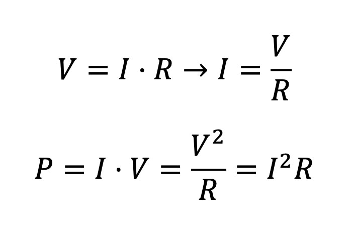
 Let’s try to explain this in a simple way using the well-known formula of Ohm’s Law and its corollaries in the form of power:
The first formula, Ohm’s Law, says that voltage (V) and current (I) are proportional to a constant (R) that is commonly known as resistance. This law can be used for either Direct Current (DC), or Alternate Current (AC). The second formula is simply multiplication of both variables to see the quadratic dependence of the voltage and current on power (double the voltage or current, provides quadruple the power).
We can see that if we want to increase the power delivered by the electric system (battery) of our car, we have two options: Either we increase voltage (V) or we increase current (I), since the load – or resistance – of our system is (R) and is constant for a car and given conditions.
Although the aeronautical industry uses automotive industry concepts for electrification, it will be necessary to redesign some essential elements, such as inverters, so they reach voltages of 900 Vdc or higher, thanks to advances in GaN and SiC.
Between increasing V or increasing I, there are some pros and cons that make engineers opt for one or the other alternative. Roughly speaking, the disadvantage of increasing V is that the conductors and subcircuits must be better insulated to prevent electric arcs or voltage discharges to the vehicle chassis, while the disadvantage of increasing I is that it is necessary to increase the effective cross-sectional area of the conductors to be able to transport the greater current that has to reach the subsystems.
And this is where the synergies of the aeronautical world with the automotive world begin, being that – as suggested in the title – in the short term we want to save fuel by carrying less weight. And in the mid to long term, we want to avoid consuming fuel to decarbonise the planet and reduce our carbon footprint as much as possible.
Circuits at higher voltages than the classic 12V used in the past (and still used for starter circuits) in our combustion and hybrid vehicles, are inadequate for this purpose. And that is why the automotive industry started to look for an optimal solution between a mounted battery pack, the required insulation, the resulting operating voltages and the inverters necessary to change from alternate current to direct current during the process of charging, discharging, and regenerative braking.
Many manufacturers placed that point around 400 V for electric vehicles (hybrids, plug-in hybrids or fully electric), since the technology of Silicon (Si) and Insulated Gate Bipolar Transistors (IGBT) was very consolidated thanks to previous work in the soft starters for single and three-phase motors for High Voltage Alternate Current (HVAC) present in various industrial machines. The problem began to occur when a 100 km range was not enough, and it was not possible to charge in less than an hour.
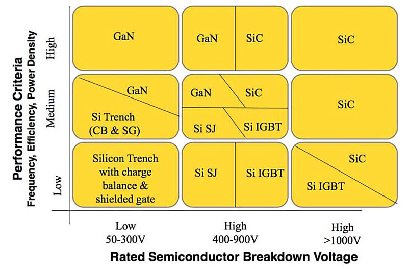
Thus, higher voltage battery packs were born to provide greater range, accompanied by another type of technology that can no longer be based exclusively on Silicon, but on Silicon Carbide (SiC) and Gallium Nitride (GaN), which enable electronic developers to work in the 400-900 V range with high efficiency, defined as low heat dissipation in the delivery of the battery to the vehicle’s electric motors, as well as high efficiency in the Wall Mount charger that will deliver the power from home mains to battery to recharge the battery when plugged in.
Illustration 1. Si, IGBT, SiC and GaN comparison (Source: PntPower.com)
We will not go into much detail about why it’s possible to work at higher voltages with SiC or GaN than with Si, but the main reason is because they are devices known as Wide BandGap (WBG). The higher value in SiC and GaN to pass an electron from the valence band to the conduction band is what makes it possible for them to have a higher breakdown voltage and, therefore, to work at voltages higher than Si.
And what is happening in the aeronautical world? Simply the same things that happened in the automotive world 24 years ago: We want hybrid or electric airplanes that help us decarbonise and reduce our CO2 per trip. The challenge is that the power required to fly a light aircraft is not comparable to that required to move a car, which presumable will require new battery technologies (higher energy density per cubic centimetre and lighter weight), new materials for distribution, electrical insulation, and of course, increase in the current values of the “typical” voltages for aircraft, which are usually 28 V in direct voltage and 115 V in alternating voltage at 400 Hz.
Again, the aeronautical industry will be able to take the concepts of the automotive industry, adapting and improving them for its working constraints. But what does seem clear is that new inverters must be designed in the 250-600 Vdc range, which in the former stages (hybrid aircraft) bleed the inversion in engines at 115 Vac @ 400 Hz, which comply with all applicable aeronautical regulations (DO-160, MIL-STD-704, etc.) to later go to a fully electric model airplane, possibly at a voltage higher than 900 Vdc, where SiC technology has to be researched and polished as Si-based technology was decades ago.
Some aeronautical companies are already prepared to design this new aeronautical future and make it a reality. Will you join us?


