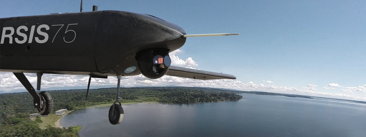
Some say that an unmanned aircraft (drone, UAV, UAS or RPAS) is nothing more than a flying machine carrying a camera. And this is essentially true; but then it is also true that cameras are nothing more than mere data collectors and, in turn, data is nothing more than noise that needs to be processed. They are all part of a chain where all links must work perfectly. On this occasion, we are going to focus on sensors.
In Intelligence, Surveillance and Reconnaissance (ISR) missions with UAS, the choice of the image sensor is crucial. Selecting and integrating specific sensors or cameras for observation in unmanned aerial systems (UAS) requires a well-calculated balance between many limiting factors (which are not always obvious) imposed by the aircraft, by the sensor’s own capabilities, by the operational characteristics of the aircraft, and even by the policies of the country where the sensor is manufactured.
Different UAS missions have different constraints and different objectives; the broad range of requirements that define the best possible sensor narrows down the available options.
In general, the aim is always to install the best possible sensor into an aerial system, which is already fairly well adapted and limited to a specific type of mission (for more details on the importance of a mission-adapted design in an UAS, please refer here to the post “UAS and zero-sum systems” ).
In the case of UAS for surveillance missions, it is usually essential that the image sensor is integrated in a gyro-stabilised platform with a fairing and with independent movements to the aircraft, commonly called a gimbal, ball or turret.
Since different missions have different constraints, and since the same mission may have several different objectives, the range of requirements that define the “best possible sensor” are hugely variable. However, for practical and logical reasons, one cannot have an infinite number of sensors. A compromise must therefore always be reached in the choice of sensor.
As mentioned, the compromise in the choice of a sensor takes into account, many types of limitations imposed by the system, by the sensor itself and even by the type of operation.
The main limiting factors are:
Weight and size limitations.
Clearly, the sensor must be integrated within the aircraft (although part of the sensor usually protrudes outside the aircraft fuselage) in such a way that it does not disproportionately alter flight aerodynamics or pose a problem or hazard to other aircraft functions.
Similarly, the weight of the sensor must be within the aircraft’s permissible load limits. Other limitations in terms of positioning are also encountered on the basis of the sensor’s weight: the sensor can only be placed in a limited range of positions, so that the corresponding change in the centre of gravity (CoG) of the aircraft remains within the tolerable limits stipulated by the manufacturer’s design. A sensor being placed too far forward or back could lead to an unavoidable loss of the aircraft in flight.
Communication, power and cooling limitations.
The sensor needs to communicate, receive power and be cooled. Cooling is usually not a problem for the part of the ball that sticks out of the fuselage, but for the internal part the corresponding air inlets and outlets need to be planned to avoid any overheating or a shortening of its life.
The power supply and communication with other elements inside the aircraft are resolved by means of the corresponding wiring. Nevertheless, we must consider these pathways, as well as the less obvious, but almost unavoidable, signal shielding (caused by screws, metal plates or carbon fibre plates) and possible areas of cross interference. Connectors and contra-connectors must also be considered, as they are not always optimised for this particular use which in order to offer greater reliability, may occupy more space than is desirable or planned.
Mechanical limitations of the sensor.
The main mechanical movements associated with a gyro-stabilised gimbal are called PTZ, which refers to Pan (horizontal movement of the camera), Tilt (vertical movement of the camera) and Zoom (movement of the camera lenses to increase or decrease its focal length).
The first two require powerful and precise motors that take up space and that must be perfectly synchronised with each other to achieve a smooth (rather than jerky) movement of the camera. The zoom motor is usually incorporated into the camera itself, but it still needs to be integrated in terms of control signals.
A good sensor should have a continuous 360° pan capability, which means it is able to rotate indefinitely in one direction without cables getting tangled around the axis. This is achieved using electrical contacts that rotate around the axis; however, this requires more space and complexity than simply connecting the camera with wires.
In terms of the tilt, 90° is usually sufficient (to look from the horizon to the vertical), but a little extra is usually added, beyond both the horizontal and the vertical, to compensate for the aircraft’s continuous pitching movements.
Limitations of gyro-stabilisation.
A dedicated sensor for observation and surveillance missions used in RPAS must be gyro-stabilised.
This means two things:
Firstly, the sensor must be protected from any unwanted movements, such as the aircraft’s normal vibrations produced by the engine, air friction and other sources. There is nothing worse than investing in high-capacity image magnification and then making the image useless due to the sensor being subjected to excessive movement (like looking at a distant point holding binoculars with shaky hands). This effect is usually mitigated using mechanical isolators made from flexible material (like the silent blocks that isolate a car from engine vibrations) placed between the gimbal and the aircraft’s structure. Several phases of isolation may be necessary: a vibration isolation platform of one type may be included in another vibration isolation platform of another type.
The sensor must also be isolated from normal aircraft motion corresponding to flight attitude corrections in roll, pitch and yaw for a stabilised flight, as well as from any movements necessary to change flight paths or those involved in orbiting the target of interest.
Secondly, the sensor must have the ability to move independently of the aircraft by means of a control executed by the surveillance operator, allowing it to maintain its focus on a fixed or mobile external point without being affected by the aircraft’s flight attitude.
This is necessary not only in terms of the image quality achieved, but also as an aid to reduce the workload of the sensor’s operator.
Stabilisation, defined as the level of stabilisation imparted to the camera by the gimbal, is measured in microradians, and is achieved by integrating the gimbal’s accelerometers, magnetometers and gyroscopes, which maintain a stable camera position regardless of the aircraft’s attitude.
This stabilisation is also carried out or increased by the application of video processing algorithms that systematically compare consecutive frames of captured video. When displacement movements appear between one frame and the next in a scene where there is supposed to be no displacement, then the software reverses the X and Y axes of motion and tries to keep the image centred.
Image limitations.
A surveillance sensor providing only a video image in a single format may be insufficient for most ISR missions. Ideally, the sensor should provide other types of images in addition to the visual (electro-optical) image, such as infrared, in order to build a process of detection, recognition and identification (DRI) of targets and achieve greater power. It is also desirable that it includes some zoom capability to allow both panoramic observation and detailed observation using the same camera. Although not essential, other options that are very useful in surveillance missions, such as laser rangefinders to establish precise distances to the target, are also valuable.
Functionality limitations.
In a normal observation mission, the operator must be aware of several screens at the same time (especially if the sensor transmits different types of images). This makes their workload very high and puts a lot of strain on the eyes.
Some sensors incorporate automatic target generation features that indicate objects that may be considered of interest for the operation. These functionalities are usually based on instantaneous image processes that can be performed on the same aerial platform or that require processing on the ground. In any case, this additional information must be displayed and be of use on the ground control station (GCS) screens immediately or in quasi-real time. When the sensor performs the process, it must be taken into account whether the processor is small and powerful enough to fit in the gyro-stabilised platform itself (which is the current trend) or whether – as is the case in slightly older models – it requires a built-in external processor that must also be integrated.
Geo-tracking (communicating geographic coordinates to the system so that the camera points at them in a stabilised way) and video tracking (indicating a fixed point of interest on the received video image so that the camera points at that spot in a stabilised way) functionalities are very valuable in all surveillance missions. These functionalities require the integration of the sensor with its accelerometers and coordination with a satellite positioning system (after all, what these functionalities do is allocate GPS coordinates to the image that would be captured by the camera with a certain pan and tilt position, based on the GPS coordinates of the aircraft’s location).
Operating limitations.
Not all cameras are suitable for all missions. Obviously, the better the camera’s features, the greater variety of operations it can undertake. Certain types of missions require certain types of cameras and capabilities. For example, surveillance missions in the jungle or areas with lots of fog require the use of various spectra, including short-wave infrared (SWIR), for which gaseous water vapour formations are transparent. Similarly, a purely visual (electro-optical) sensor is not able to detect anything during night-time missions.
Marketing limitations.
The sensors discussed here may have qualities or belong in categories restricted for defence uses only, which can prevent or limit their integration into a system intended for civilian use. This is especially the case with high-resolution infrared cameras, where HD resolution (High Definition: 720 pixels) is considered to be for defence use only. Their sale is therefore regulated by export rules for dual-use items. (Dual-use items are goods that, as they are or with only minimal changes, can be used as weapons, and which are therefore regulated and controlled throughout their commercial chain of ownership by means of an end-user certificate and the corresponding marketing permits required by the country of origin.)
Manufacturer service limitations.
These powerful gyro-stabilised sensors are usually quite expensive and are not always easy to integrate into another equally complex system, such as an UAS. Therefore manufacturers need to have a minimum amount of flexibility in their conditions before working with any of their products. Of course, once the first unit has been fully integrated, 90% of incidents are already solved for subsequent units. That is why initial integrations require special attention and availability of resources, which are sometimes not within the integrator’s reach.
Political limitations.
Countries where dual-use components are purchased do not always get along well with the destination country of the device these components are integrated in. To make it even more complicated, these situations change over time and come and go depending on the political relations between the three countries involved (the component’s country of origin, the country performing the integration of the component, and the destination country). Thus, a perfectly good component that meets all the requirements can sometimes be rejected because the country of origin is in conflict with the country of destination. The worst-case scenario is if this situation occurs once the component has already been acquired and integrated.

#uas


